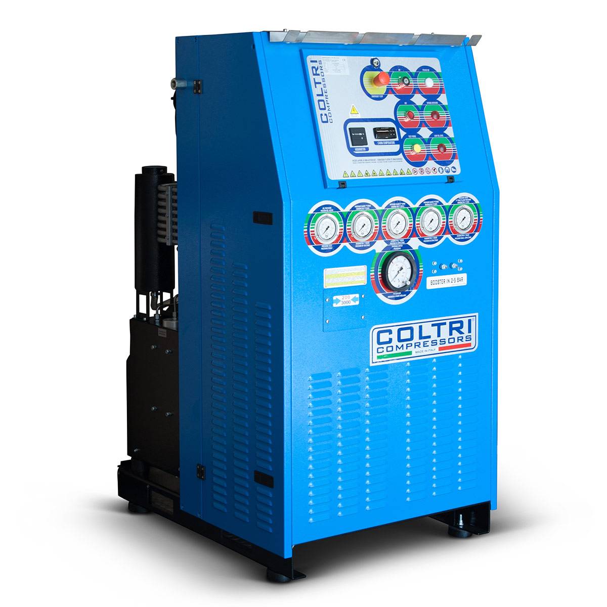
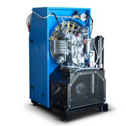
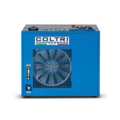
The OPEN model is a high pressure booster compressor based on the efficient mechanics of the MCH 36 pumping unit. The control and command components, essential for daily operation, are arranged on the front panel with easy access.
H : 1530 mm – W : 790 mm – D : 1052 mm
H : 60.24 in – W : 31.10 in – D : 41.42 in
Technical specifications
Drive: Three-phase Electric Motor
Flow rate: From 15,5 m3/h (29 PSIG) to 36,6 m3/h (73 PSIG ASCOM)
Operating pressure: 232 – 300 – 330 – 420 bar or 3365 – 4351 – 4786 – 6092 PSIG
Net weight: 375 kg – 827 Lbs
Noise level: 78 db
Drive: Three-phase Electric Motor
Flow rate: From 15,5 m3/h (29 PSIG) to 36,6 m3/h (73 PSIG ASCOM)
Operating pressure: 232 – 300 – 330 – 420 bar or 3365 – 4351 – 4786 – 6092 PSIG
Net weight: 375 kg – 827 Lbs
Noise level: 78 db
 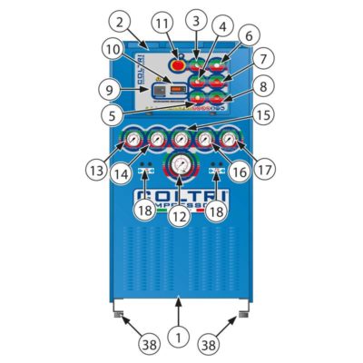  |
Components
1. Frame
2. Control panel
3. On pushbutton
4. Off pushbutton
5. Condensate drain pushbutton
6. Power indicator light
7. Wrong rotation direction alert
8. Oil level warning light
9. Operating hours counter
10. Cabinet interior / cooling air temperature
11. Emergency pushbutton
12. Automatic shutdown pressure switch
13. Oil pressure gauge
14. 1st stage pressure gauge
15. 2nd stage pressure gauge
16. 3rd stage pressure gauge
17. 4th stage pressure gauge / use pressure
18. Pressurised gas output
19. Oil level gauge
20. Oil drain valve
21. Purifier filter
22. Condensate collection container
23. Condensate collection tank
24. Engine
25. Compressor
26. Air filter
27.Final condensate separator
28. 1st Stage
29. 2nd Stage
30. 3rd Stage
31. 4th Stage
32. Crankcase
33. Oil filler plug
34. Safety valve
35. Maintenance valve
36. Cooling fan
37. Belt
38. Anti-vibration devices
39. Condensate separator
40. Gas input 2÷ 5bar
|
 |
PRESSURE CIRCUIT Components
1. Aspiration filter
2. Intake valve 1st stage
3. Discharge valve 1st stage
4. Pressure switch
5. Safety valve – 1st stage
6. Pressure gauge 1st stage
7. Cooling pipe 1st-2nd stage
8. Intake valve 2nd stage
9. Discharge valve 2nd stage
10. Cooling pipe 2nd-3rd stage
11. Condensate separator
12. Safety valve – 2nd stage
13. Pressure gauge 2nd stage
14. Intake valve 3rd stage
15. Discharge valve 3rd stage
16. Cooling pipe 3rd-4th stage
17. Condensate separator
18. Safety valve – 3rd stage
19. Pressure gauge 3rd stage
20. Intake valve 4th stage
21. Discharge valve 4th stage
22. Final cooling pipe
23. Condensate separator
24. Non return valve
25. Active carbon filter
26. Safety valve
27. Pressure gauge 4th stage
28. Pressure maintaining valve
29. Pressure switch
30. Flex hoses
|
|
STANDARD EQUIPMENT:
ELECTRICAL CABINET
with hour counter
OIL PUMP
PRESSURE GAUGE
interstage control+input pressure
INPUT PRESSURE SWITCH
with automatic restart
|
RESTART
AUTOMATIC CONDENSATE DRAIN
THERMOSTAT
Cabin temperature thermostat/auto shut-off
PHASE CONTROLLER
that prohibits reverse rotation
OIL LEVEL CHECK
switch/auto shut-off
|
Related products
BOOSTER


